“循迹”的版本间的差异
来自Labplus盛思维基百科
Tangliufeng(讨论 | 贡献) (→技术参数) |
Labplus课程组(讨论 | 贡献) (→Arduino示例) |
||
| 第25行: | 第25行: | ||
== 使用教程 == | == 使用教程 == | ||
在安装循迹模块时约距离循迹线1CM左右 | 在安装循迹模块时约距离循迹线1CM左右 | ||
| − | === | + | === <small>Python示例</small> === |
<pre style="color:blue"> | <pre style="color:blue"> | ||
//程序功能:根据循迹传感器两个红外对管的不同状态,控制两个电机的状态// | //程序功能:根据循迹传感器两个红外对管的不同状态,控制两个电机的状态// | ||
| 第74行: | 第74行: | ||
} | } | ||
</pre> | </pre> | ||
| + | |||
=== 应用示例 === | === 应用示例 === | ||
* [[Example_2 bluebit循迹小车|bluebit循迹小车]] | * [[Example_2 bluebit循迹小车|bluebit循迹小车]] | ||
2018年4月20日 (五) 16:16的版本
概述
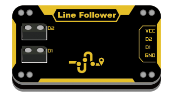
可用于循迹线检测,当检测到黑色时,输出高电平,检测白色时,输出低电平。
基于红外反射原理,红外发射二极管不断发射红外线,红外光电三极管接收反射回来的红外光。由于白色对红外反射强,黑色对红外反射弱,故此可检测黑、白线。
技术参数
- 工作电压:VCC 3.3-5V
- 检测范围:1-3cm
- 模块尺寸:24x46x7.5mm
引脚定义
| VCC | 电源 |
| D1 | 对应D1红外接收触发值 |
| D2 | 对应D2红外接收触发值 |
| GND | 地 |
使用教程
在安装循迹模块时约距离循迹线1CM左右
Python示例
//程序功能:根据循迹传感器两个红外对管的不同状态,控制两个电机的状态//
//红外对管1  红外对管2  电机1  电机2//
//    1          1      不转   不转 //
//    1          0      不转   转   //
//    0          1      转     不转 //
//    0          0      转     转   //
int find1Pin =2;
int find2Pin =3;
int motor1Pin =7;
int motor2Pin =8;
int a,b;
void setup() {
  Serial.begin(9600);
  pinMode(find1Pin, INPUT);
  pinMode(find2Pin, INPUT);
  pinMode(motor1Pin, OUTPUT);
  pinMode(motor2Pin, OUTPUT);
}

void loop() {
  // put your main code here, to run repeatedly:
  a=digitalRead(find1Pin);
  b=digitalRead(find2Pin);
  Serial.println(a);
  Serial.println(b);
  if((a==1)&&(b==1))
  {
    digitalWrite(motor1Pin,LOW);
    digitalWrite(motor2Pin,LOW);
  }
  if((a==1)&&(b==0))
  {
    digitalWrite(motor1Pin,LOW);
    digitalWrite(motor2Pin,HIGH);
  }
  if((a==0)&&(b==1))
  {
    digitalWrite(motor1Pin,HIGH);
    digitalWrite(motor2Pin,LOW);
  }
  if((a==0)&&(b==0))
  {
    digitalWrite(motor1Pin,HIGH);
    digitalWrite(motor2Pin,HIGH);
  }
}
应用示例
版本历史记录
| Version | Date | Note [+]新增[-]删除[^]修复 |
|---|---|---|
| V2.0 |
