“端口扩展”的版本间的差异
来自Labplus盛思维基百科
Tangliufeng(讨论 | 贡献) (→MicroPython示例) |
Tangliufeng(讨论 | 贡献) (→MicroPython示例) |
||
| 第32行: | 第32行: | ||
from microbit import * | from microbit import * | ||
| − | def | + | def extIOInit(pin, mode): |
| − | + | i2c.write(0x20, bytearray([3])) | |
| − | + | mode_old=i2c.read(0x20, 1) | |
| − | + | mode_new = 0 | |
| − | + | if mode == 1: | |
| + | mode_new = mode_old[0] | (1 << pin) | ||
| + | elif mode == 0: | ||
| + | mome_new = mode_old[0] | (~(1 << pin)) | ||
| + | cfg= bytearray([0x03,mode_new]) | ||
| + | i2c.write(0x20, cfg) | ||
| − | + | def readExtendedIO(pin): | |
| − | + | reg=bytearray([0]) | |
| − | i2c.write(0x20, | + | i2c.write(0x20, reg) |
| + | dat=i2c.read(0x20, 4) | ||
| + | return (dat[0] >> pin) & 0x01 | ||
| − | + | def writeExtendedIO(pin, output): | |
| − | + | reg=bytearray([1]) | |
| − | + | i2c.write(0x20, reg) | |
| − | + | stat_old=i2c.read(0x20, 3) | |
| − | + | stat_new = 0 | |
| − | + | if output == 1: | |
| − | + | stat_new = stat_old[0] | (1 << pin) | |
| − | + | elif output == 0: | |
| + | stat_new = stat_old[0] & (~(1 << pin)) | ||
| + | cfg = bytearray([0x01, stat_new]) | ||
| + | i2c.write(0x20,cfg) | ||
| + | extIOInit(0,0) #pin io0 set output mode | ||
| + | extIOInit(1,0) #pin io1 set output mode | ||
| + | extIOInit(6,1) #pin io6 set input mode | ||
| + | while True: | ||
| + | buttonVal = readExtendedIO(6) | ||
| + | if buttonVal == 0: | ||
| + | writeExtendedIO(0, 1) | ||
| + | writeExtendedIO(1, 1) | ||
| + | elif buttonVal == 1: | ||
| + | writeExtendedIO(0, 0) | ||
| + | writeExtendedIO(1, 0) | ||
| + | sleep(100) | ||
</pre> | </pre> | ||
=== 图形化示例 === | === 图形化示例 === | ||
2018年3月19日 (一) 17:27的版本
概述
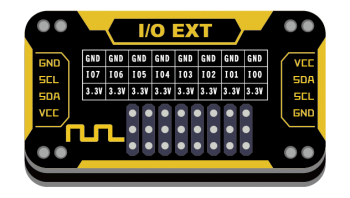
当主控的引脚不够用时,可用该模块通过I2C接口拓展I/O口,最大支持8个I/O引脚拓展。
技术参数
- 工作电压:VCC 3.3-5V
- I2C数字信号通讯
- 最大支持8个I/O端口拓展
- 模块尺寸:24x46x7.5mm
引脚定义
| VCC | 电源 |
| SDA | I2C数据 |
| SCL | I2C时钟 |
| GND | 地 |
使用教程
详细的寄存器操作和指令说明,可查阅芯片手册点击下载
连接示意图
Arduino示例
MicroPython示例
from microbit import *

def extIOInit(pin, mode):
    i2c.write(0x20, bytearray([3]))
    mode_old=i2c.read(0x20, 1)
    mode_new = 0
    if mode == 1:
        mode_new = mode_old[0] | (1 << pin)
    elif mode == 0:
        mome_new = mode_old[0] | (~(1 << pin))
    cfg= bytearray([0x03,mode_new])
    i2c.write(0x20, cfg)

def readExtendedIO(pin):
    reg=bytearray([0])
    i2c.write(0x20, reg)
    dat=i2c.read(0x20, 4)
    return (dat[0] >> pin) & 0x01

def writeExtendedIO(pin, output):
    reg=bytearray([1])
    i2c.write(0x20, reg)
    stat_old=i2c.read(0x20, 3)
    stat_new = 0
    if output == 1:
        stat_new = stat_old[0] | (1 << pin)
    elif output == 0:
        stat_new = stat_old[0] & (~(1 << pin))
    cfg = bytearray([0x01, stat_new])
    i2c.write(0x20,cfg)


extIOInit(0,0)  #pin io0 set output mode
extIOInit(1,0)  #pin io1 set output mode
extIOInit(6,1)  #pin io6 set input mode
while True:
    buttonVal = readExtendedIO(6)
    if buttonVal == 0:
        writeExtendedIO(0, 1)
        writeExtendedIO(1, 1)
    elif buttonVal == 1:
        writeExtendedIO(0, 0)
        writeExtendedIO(1, 0)
    sleep(100)
