“Extend:bitⅡ”的版本间的差异
来自Labplus盛思维基百科
Tangliufeng(讨论 | 贡献) |
Tangliufeng(讨论 | 贡献) |
||
| 第44行: | 第44行: | ||
<big>Step4.</big>蜂鸣器:''在使用时蜂鸣器跳线帽须接上''<br /> | <big>Step4.</big>蜂鸣器:''在使用时蜂鸣器跳线帽须接上''<br /> | ||
[[文件:蜂鸣器 extendbit2.png|300px|无框|左]]<br /><br /><br /> | [[文件:蜂鸣器 extendbit2.png|300px|无框|左]]<br /><br /><br /> | ||
| − | <big>Step5.</big> | + | <big>Step5.</big>RGB灯:2个串联灯珠,使用P16引脚控制 |
{| style=" background-color:#ffffcc;" cellpadding="0" | {| style=" background-color:#ffffcc;" cellpadding="0" | ||
| <small>注意灯珠启始是从"0"开始的</small> | | <small>注意灯珠启始是从"0"开始的</small> | ||
2018年4月24日 (二) 15:27的最新版本
概述
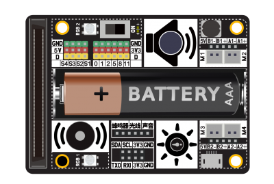
microbit拓展板,支持4路电机驱动、4路舵机驱动。内置声音传感器、光线传感器、无源蜂鸣器、2颗级联全彩RGB灯珠。
技术参数
- DC接口:Micro USB 可循环充电
- 采用18650锂电池
- PCI插槽,可接入micro:bit作为主控
- 支持4路舵机驱动和4路电机驱动,采用I2C通讯不占用引脚资源
- 拓展microbit引脚P0/1/2/5/8/11、I2C、UART
- 级联2颗全彩RGB灯珠ws2812
- 内置光线、声音传感器、无源蜂鸣器
- 最大负载电流:1.2A
引脚定义
| 内置 | micro:bit引脚 |
|---|---|
| 无源蜂鸣器 | P0 |
| 光线传感器 | P1 |
| 声音传感器 | P2 |
| 全彩RGB灯 | P16 |
| 电机舵机驱动 | I2C |
| UART | RXI->P14 TXO->P15 |
快速入门
Step1.教程:microbit怎么编程下载?
Step2.电机驱动:extend:bitⅡ插上micro:bit,接上马达。M1/M2/M3/M4,4路电机驱动,调速0~255
Step3.舵机驱动:S1/S2/S3/S4,4路舵机驱动;角度0~180;
Step4.蜂鸣器:在使用时蜂鸣器跳线帽须接上
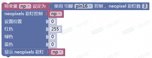
Step5.RGB灯:2个串联灯珠,使用P16引脚控制
| 注意灯珠启始是从"0"开始的 |
Step6.光线、声音传感器:光线使用P1,声音使用P2在使用时光线、声音跳线帽须接上
Step7.P0/P1/P2/P5/P8/P11拓展引脚使用,注意在使用时候,当用到P0/P1/P2,需要取下对应引脚的跳线帽,断开extendbit与microbit的引脚连接!
注意 重新装载18650锂电池,第一次需要接上USB激活锂电池!
Python各功能测试例程
示例测试各模块功能:
1.上电蜂鸣器发出1KHz,持续1秒声音
2.RGB灯依次红绿蓝显示
3.串口打印输出声音和光线采样数据
4.4路电机驱动正反转和4路舵机180度摆动,间隔1秒
from microbit import *
import music
import neopixel

PCA9685_ADDRESS = 0x41   #device address

#define register
MODE1 = 0x00
MODE2 = 0x01
SUBADR1 = 0x02
SUBADR2 = 0x03
SUBADR3 = 0x04
PRESCALE = 0xFE
LED0_ON_L = 0x06
LED0_ON_H = 0x07
LED0_OFF_L = 0x08
LED0_OFF_H = 0x09
ALL_LED_ON_L = 0xFA
ALL_LED_ON_H = 0xFB
ALL_LED_OFF_L = 0xFC
ALL_LED_OFF_H = 0xFD

STP_CHA_L = 2047
STP_CHA_H = 4095
STP_CHB_L = 1
STP_CHB_H = 2047
STP_CHC_L = 1023
STP_CHC_H = 3071
STP_CHD_L = 3071
STP_CHD_H = 1023

# Servos define
S1 = 0x01
S2 = 0x02
S3 = 0x03
S4 = 0x04
# Motors define
M2 = 0x1
M1 = 0x2
M4 = 0x3
M3 = 0x4

# Steppers define
STP_M1 = 0x1
STP_M2 = 0x2
FORWARD = 0
REVERSAL = 1

# device init
def initPCA9685():
    i2c.write(PCA9685_ADDRESS, bytearray([MODE1, 0x00]))
    setFreq(50)
    for idx in range(0, 16, 1):
        setPwm(idx, 0 ,0)
    #initialized = true

# function: motorRun()
# @param motor:  M1A, M1B, M2A, M2B
# @param speed1: -255 - 255  0 is stop
def MotorRun(Motors, speed):
    speed = speed * 16  # map 255 to 4096
    if (speed >= 4096):
        speed = 4095
    if (speed <= -4096):
        speed = -4095
    if (Motors <= 4 and Motors > 0):
        pp = (Motors - 1) * 2
        pn = (Motors - 1) * 2 + 1
        if (speed >= 0):
            setPwm(pp, 0, speed)
            setPwm(pn, 0, 0)
        else :
            setPwm(pp, 0, 0)
            setPwm(pn, 0, -speed)

# function: motorRun()
# @param Servos:  S1, S2, S3, S4
# @param degree:  0-180
def Servo(Servos, degree):
    # 50hz: 20,000 us
    v_us = (degree * 1800 / 180 + 600)  # 0.6 ~ 2.4ms
    value = int(v_us * 4096 / 20000)
    setPwm(Servos + 7, 0, value)

#set frequency
def setFreq(freq):
    #Constrain the frequency
    prescaleval = int(25000000/(4096*freq)) - 1
    #prescale = prescaleval;  #Math.Floor(prescaleval + 0.5)
    i2c.write(PCA9685_ADDRESS, bytearray([MODE1]))
    oldmode = i2c.read(PCA9685_ADDRESS, 1)
    newmode = (oldmode[0] & 0x7F) | 0x10  # sleep
    i2c.write(PCA9685_ADDRESS, bytearray([MODE1, newmode])) # go to sleep
    i2c.write(PCA9685_ADDRESS, bytearray([PRESCALE, prescaleval]))  # set the prescaler
    i2c.write(PCA9685_ADDRESS, bytearray([MODE1, oldmode[0]]))
    sleep(4)
    i2c.write(PCA9685_ADDRESS, bytearray([MODE1, oldmode[0] | 0xa1]))

# function: setPwm()
def setPwm(channel, on, off):
    if (channel >= 0 and channel <= 15):
        buf = bytearray([LED0_ON_L + 4 * channel, on & 0xff, (on >> 8) & 0xff, off & 0xff, (off >> 8) & 0xff])
        i2c.write(PCA9685_ADDRESS, buf)

# function: setStepper()
# for 2 phase 4 line step motor
# @param stpMotors : STP_M1, STP_M2
# @param dir: FORWARD REVERSAL
# @param speed: 25 - 200
def setStepper(stpMotors, dir, speed):
    spd = speed
    #print(spd)
    setFreq(spd)
    if (stpMotors == 1): #step motor 1
        if (dir): # forward rotating
            setPwm(0, STP_CHA_L, STP_CHA_H)
            setPwm(1, STP_CHB_L, STP_CHB_H)
            setPwm(2, STP_CHC_L, STP_CHC_H)
            setPwm(3, STP_CHD_L, STP_CHD_H)
        else:  # reversal rotating
            setPwm(3, STP_CHA_L, STP_CHA_H)
            setPwm(2, STP_CHB_L, STP_CHB_H)
            setPwm(1, STP_CHC_L, STP_CHC_H)
            setPwm(0, STP_CHD_L, STP_CHD_H)
    elif (stpMotors == 2): #step motor 2
        if (dir):
            setPwm(4, STP_CHA_L, STP_CHA_H)
            setPwm(5, STP_CHB_L, STP_CHB_H)
            setPwm(6, STP_CHC_L, STP_CHC_H)
            setPwm(7, STP_CHD_L, STP_CHD_H)
        else:
            setPwm(7, STP_CHA_L, STP_CHA_H)
            setPwm(6, STP_CHB_L, STP_CHB_H)
            setPwm(5, STP_CHC_L, STP_CHC_H)
            setPwm(4, STP_CHD_L, STP_CHD_H)

#test code
initPCA9685()
# setStepper(STP_M1, REVERSAL, 80)  # test step motor

np = neopixel.NeoPixel(pin16, 3)

music.pitch(1000,1000)
for i in range(0,3):
    np[i]=(255,0,0)
np.show()
sleep(1000)
for i in range(0,3):
    np[i]=(0,255,0)
np.show()
sleep(1000)
for i in range(0,3):
    np[i]=(0,0,255)
np.show()
sleep(1000)
np.clear()
t =running_time()
flag=0
while True:
    print('light:',pin1.read_analog(),' Sound',pin2.read_analog())
    sleep(20)
    if (running_time() - t) > 2000:
        t = running_time()
        flag= not flag
        if flag:
            MotorRun(M1, 255)
            MotorRun(M2, 255)
            MotorRun(M3, 255)
            MotorRun(M4, 255)
            #servo test
            for i in range(1, 5, 1):
                Servo(i, 180)
        else:
            MotorRun(M1, -255)
            MotorRun(M2, -255)
            MotorRun(M3, -255)
            MotorRun(M4, -255)
            for i in range(1, 5, 1):
                Servo(i, 0)
应用案例
- Example_1 extend:bitⅡ音量计
- Example_2 extend:bitⅡ音乐盒
- Example_3 extend:bitⅡ循迹小车
- Example_4 extend:bitⅡ变色龙
- Example_5 extend:bitⅡ植物检测器
版本历史记录
| Version | Date | Note [+]新增[-]删除[^]修复 |
|---|---|---|
| V1.2 | 2018/04/24 | [^] 修改外观、布局 [^] 电池座改成18650 [^] ws2812灯珠改成2颗 [^] PCA9685 I2C地址由0x40改为0x41 |


