“数码管”的版本间的差异
来自Labplus盛思维基百科
Tangliufeng(讨论 | 贡献) |
(→使用教程) |
||
| (未显示3个用户的10个中间版本) | |||
| 第21行: | 第21行: | ||
== 使用教程 == | == 使用教程 == | ||
| + | === <font size="3">掌控板</font> === | ||
| + | {| | ||
| + | |- | ||
| + | | [[文件:数码管2.png |900px|居中|无框]] | ||
| + | |} | ||
| + | |||
=== Arduino示例 === | === Arduino示例 === | ||
| − | [ | + | |
| + | [[:File:TM1650.rar|TM1650数码管库下载]] | ||
<pre style="color:blue"> | <pre style="color:blue"> | ||
//程序功能:数码管每秒显示8.8.8.8. 0.5S// | //程序功能:数码管每秒显示8.8.8.8. 0.5S// | ||
#include <Wire.h> | #include <Wire.h> | ||
| − | #include | + | #include "TM1650.h" |
#include <Arduino.h> | #include <Arduino.h> | ||
TM1650 d; | TM1650 d; | ||
| 第51行: | 第58行: | ||
</pre> | </pre> | ||
| − | === | + | === <font size="3">Python示例</font> === |
| − | + | {| | |
| − | [[文件:数码管连接.jpg| | + | |- |
| + | |[[文件:数码管连接.jpg|700px|居中]] | ||
| + | |- | ||
| + | |style="text-align:center"|连接图 | ||
| + | |} | ||
<pre style="color:blue"> | <pre style="color:blue"> | ||
from microbit import * | from microbit import * | ||
| 第92行: | 第103行: | ||
elif temp < 1000: | elif temp < 1000: | ||
i2c.write(0x34, bytearray([_TubeTab[0x11]])) | i2c.write(0x34, bytearray([_TubeTab[0x11]])) | ||
| + | |||
| + | def tm1650Clear(): | ||
| + | for i in range(0, 4): | ||
| + | i2c.write(0x34+i, bytearray([_TubeTab[0x10]])) | ||
tm1650Init() | tm1650Init() | ||
| 第105行: | 第120行: | ||
tm1650DisplayInt(1111) | tm1650DisplayInt(1111) | ||
sleep(1000) | sleep(1000) | ||
| + | </pre> | ||
| + | === 图形化示例 === | ||
| + | {| | ||
| + | |- | ||
| + | |连接方法同上 <br/> 程序功能:数码管的各个数位递增 | ||
| + | |- | ||
| + | |[[file:数码管.png|900px|left|无框]] | ||
| + | |- | ||
| + | |} | ||
| − | </ | + | == 版本历史记录 == |
| + | |||
| + | {| border="1" cellspacing="0" align="left" cellpadding="0" width="60%" style="text-align:center;" | ||
| + | |- style="text-align:center;background-color:#6fa8dc;color:#fffff;" | ||
| + | !width="10%"|Version !!width="15%"| Date !! Note <small>[+]新增[-]删除[^]修复</small> | ||
| + | |- | ||
| + | | V2.0 || || style="text-align:left"| | ||
| + | |} | ||
2020年6月30日 (二) 16:52的最新版本
概述
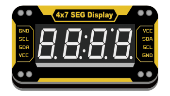
4位7段LED数码管显示,可显示整形数字
技术参数
- 工作电压:VCC 3.3-5V
- 接口方式:I2C接口
- 模块尺寸:24x46x7.5mm
引脚定义
| VCC | 电源 |
| SDA | I2C数据 |
| SCL | I2C时钟 |
| GND | 地 |
使用教程
掌控板
Arduino示例
//程序功能:数码管每秒显示8.8.8.8. 0.5S//
#include <Wire.h>
#include "TM1650.h"
#include <Arduino.h>
TM1650 d;
char line[] = {"8888"};
void setup()
{
  Wire.begin();
  d.init();  //数码管初始化
  d.displayOff(); //关闭显示
  d.displayString(line);  //输入显示字符
  d.setBrightness(2);  //设定显示亮度
  for(int i=0; i<4; i++) d.setDot(i, true);  //显示小数点
  Serial.begin(9600);
}

void loop()
{
  d.displayOn();  //显示信息
  delay(500);
  d.displayOff(); //关闭显示
  delay(500);
  Serial.print(1);
}
Python示例
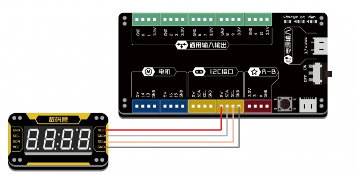
| 连接图 |
from microbit import *

_TubeTab = [
    0x3F, 0x06, 0x5B, 0x4F, 0x66, 0x6D, 0x7D, 0x07, 0x7F,
    0x6F, 0x77, 0x7C, 0x39, 0x5E, 0x79, 0x71, 0x00, 0x40]

def tm1650Init():
  i2c.write(0x24, bytearray([0x01]))
def tm1650DisplayUint(x):
  charTemp = [0, 0, 0, 0]
  x = (x if x < 10000 else 9999)
  charTemp[3] = x%10
  charTemp[2] = (x//10)%10
  charTemp[1] = (x//100)%10
  charTemp[0] = (x//1000)%10
  if x < 1000:
    charTemp[0] = 0x10
    if x < 100:
      charTemp[1] = 0x10
      if x < 10:
        charTemp[2] = 0x10
  for i in range(0, 4):
    i2c.write(0x34+i, bytearray([_TubeTab[charTemp[i]]]))
def tm1650DisplayInt(x):
  x = round(x)
  if x >= 0:
    tm1650DisplayUint(x)
  else:
    temp = (x if x > -999 else -999)
    temp = abs(temp)
    tm1650DisplayUint(temp)
    if temp < 10:
      i2c.write(0x36, bytearray([_TubeTab[0x11]]))
    elif temp < 100:
      i2c.write(0x35, bytearray([_TubeTab[0x11]]))
    elif temp < 1000:
      i2c.write(0x34, bytearray([_TubeTab[0x11]]))

def tm1650Clear():
    for i in range(0, 4):
        i2c.write(0x34+i, bytearray([_TubeTab[0x10]]))

tm1650Init()

display.off()
while True:
    tm1650DisplayInt(7777)
    sleep(1000)
    tm1650DisplayInt(8888)
    sleep(1000)
    tm1650DisplayInt(9999)
    sleep(1000)
    tm1650DisplayInt(1111)
    sleep(1000)
图形化示例
| 连接方法同上 程序功能:数码管的各个数位递增 |
版本历史记录
| Version | Date | Note [+]新增[-]删除[^]修复 |
|---|---|---|
| V2.0 |


