“数字光线”的版本间的差异
来自Labplus盛思维基百科
Labplus课程组(讨论 | 贡献) (→MicroPython示例) |
(→使用教程) |
||
| (未显示1个用户的4个中间版本) | |||
| 第7行: | 第7行: | ||
* 工作电压:VCC 3.3-5V | * 工作电压:VCC 3.3-5V | ||
* 接口方式:I2C接口 | * 接口方式:I2C接口 | ||
| − | * 光照度范围:0-65535 | + | * 光照度范围:0-65535 lux |
* 直接输出对应亮度的数字值 | * 直接输出对应亮度的数字值 | ||
* 光源依赖性弱(白炽灯,荧光灯,卤素灯,白光LED,日光灯) | * 光源依赖性弱(白炽灯,荧光灯,卤素灯,白光LED,日光灯) | ||
| 第27行: | 第27行: | ||
== 使用教程 == | == 使用教程 == | ||
| + | <font size="3.5">BH1750FVI支持单次或连续两种测量模式,每种测量模式又提供了0.5lux、1lux、4lux三种分辨率供选择。分辨力越高,一次测量所需的时间就越长。在单次测量模式时,每次测量之后传感器都自动进入Power Down模式。</font> | ||
| + | {| | ||
| + | |- | ||
| + | | :[[文件:BH1750测量模式.png|800px|左|缩略图|BH1750测量模式]] | ||
| + | |} | ||
| + | |||
| + | === <font size="3">掌控板及mPython编程</font> === | ||
| − | |||
<pre style="color:blue"> | <pre style="color:blue"> | ||
| − | # | + | #程序功能:用掌控板OLED屏显示传感器的测量值。 |
| − | from | + | </pre> |
| + | {| | ||
| + | |- | ||
| + | | [[文件:数字光线接线图.png |800px|居中|无框]] | ||
| + | |- | ||
| + | |style="text-align:center"|连接示意图 | ||
| + | |} | ||
| + | <br/> | ||
| + | |||
| + | {| | ||
| + | |- | ||
| + | | [[文件:数字光线mPython编程.png |900px|居中|无框]] | ||
| + | |- | ||
| + | |style="text-align:center"|图形化及mPython代码 | ||
| + | |} | ||
| + | <br/> | ||
| + | <br/> | ||
| + | === <font size="3">Arduino示例</font> === | ||
| + | <pre style="color:blue"> | ||
| + | /* | ||
| + | Measurement of illuminance using the BH1750FVI sensor module | ||
| + | Connection: | ||
| + | Module UNO | ||
| + | VCC <-----> 5V | ||
| + | GND <-----> GND | ||
| + | SCL <-----> A5 | ||
| + | SDA <-----> A4 | ||
| + | |||
| + | */ | ||
| + | #include <Wire.h> | ||
| + | |||
| + | #define ADDRESS_BH1750FVI 0x23 //ADDR="L" for this module | ||
| + | #define H_RESOLUTION_MODE 0x10 | ||
| + | //continuously H-Resolution Mode: | ||
| + | //Resolution = 1 lux | ||
| + | //Measurement time (max.) = 120ms | ||
| + | //Power down after each measurement | ||
| + | |||
| + | byte highByte = 0; | ||
| + | byte lowByte = 0; | ||
| + | unsigned int sensorOut = 0; | ||
| + | unsigned int illuminance = 0; | ||
| + | |||
| + | |||
| + | void setup() | ||
| + | { | ||
| + | Wire.begin(); | ||
| + | Serial.begin(115200); | ||
| + | } | ||
| + | |||
| + | void loop() | ||
| + | { | ||
| + | Wire.beginTransmission(ADDRESS_BH1750FVI); //"notify" the matching device | ||
| + | Wire.write(H_RESOLUTION_MODE); //set operation mode | ||
| + | Wire.endTransmission(); | ||
| + | |||
| + | delay(120); | ||
| + | |||
| + | Wire.requestFrom(ADDRESS_BH1750FVI, 2); //ask Arduino to read back 2 bytes from the sensor | ||
| + | highByte = Wire.read(); // get the high byte | ||
| + | lowByte = Wire.read(); // get the low byte | ||
| − | + | sensorOut = (highByte << 8) | lowByte; | |
| + | illuminance = sensorOut / 1.2; | ||
| + | Serial.print(illuminance); Serial.println(" lux"); | ||
| − | + | delay(1000); | |
| + | } | ||
| + | </pre> | ||
| + | === <font size="3">Bluebit主控</font> === | ||
| + | <pre style="color:blue"> | ||
| + | from microbit import * | ||
| + | import math | ||
| + | display.off() | ||
def getAmbientLight(): | def getAmbientLight(): | ||
| 第42行: | 第117行: | ||
t=i2c.read(0x23, 2) | t=i2c.read(0x23, 2) | ||
sleep(10) | sleep(10) | ||
| − | return t[0]*256+t[1] | + | return (t[0]*256 + t[1])/1.2 |
while True: | while True: | ||
| − | + | print('Light:',getAmbientLight()) | |
| − | + | sleep(500) | |
| + | |||
</pre> | </pre> | ||
| − | === 图形化示例 === | + | === <font size="3">图形化示例</font> === |
{| | {| | ||
|- | |- | ||
|实物连接如下图: | |实物连接如下图: | ||
|- | |- | ||
| − | |[[文件:数字光线2.png| | + | |[[文件:数字光线2.png|700px|无框|左]] |
|- | |- | ||
|程序功能:数码管显示数字光线传感器的测量值 | |程序功能:数码管显示数字光线传感器的测量值 | ||
2020年4月16日 (四) 14:28的最新版本
概述
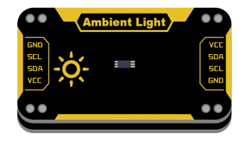
基于BH1750数字型光照度传感器集成IC。用于检测环境光线的强度,可对广泛的亮度进行1勒克斯的高精度测定。采用I2C通讯方式,操作简便。
技术参数
- 工作电压:VCC 3.3-5V
- 接口方式:I2C接口
- 光照度范围:0-65535 lux
- 直接输出对应亮度的数字值
- 光源依赖性弱(白炽灯,荧光灯,卤素灯,白光LED,日光灯)
- 受红外线影响很小
- 最小变动在±20%
- 模块尺寸:24x46x7.5mm
引脚定义
| VCC | 电源 |
| SDA | I2C数据 |
| SCL | I2C时钟 |
| GND | 地 |
使用教程
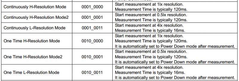
BH1750FVI支持单次或连续两种测量模式,每种测量模式又提供了0.5lux、1lux、4lux三种分辨率供选择。分辨力越高,一次测量所需的时间就越长。在单次测量模式时,每次测量之后传感器都自动进入Power Down模式。
| : |
掌控板及mPython编程
#程序功能:用掌控板OLED屏显示传感器的测量值。
| 连接示意图 |
| 图形化及mPython代码 |
Arduino示例
/*
Measurement of illuminance using the BH1750FVI sensor module
Connection:
Module        UNO
VCC    <----->    5V
GND    <----->    GND
SCL    <----->    A5
SDA    <----->    A4

*/
#include <Wire.h>

#define ADDRESS_BH1750FVI 0x23    //ADDR="L" for this module
#define H_RESOLUTION_MODE 0x10
//continuously H-Resolution Mode:
//Resolution = 1 lux
//Measurement time (max.) = 120ms
//Power down after each measurement

byte highByte = 0;
byte lowByte = 0;
unsigned int sensorOut = 0;
unsigned int illuminance = 0;


void setup()
{
	Wire.begin();
	Serial.begin(115200);
}

void loop()
{
	Wire.beginTransmission(ADDRESS_BH1750FVI); //"notify" the matching device
	Wire.write(H_RESOLUTION_MODE);     //set operation mode
	Wire.endTransmission();

	delay(120);

	Wire.requestFrom(ADDRESS_BH1750FVI, 2); //ask Arduino to read back 2 bytes from the sensor
	highByte = Wire.read();  // get the high byte
	lowByte = Wire.read(); // get the low byte

	sensorOut = (highByte << 8) | lowByte;
	illuminance = sensorOut / 1.2;
	Serial.print(illuminance);    Serial.println(" lux");

	delay(1000);
}
Bluebit主控
from microbit import *
import math
display.off()

def getAmbientLight():
  i2c.write(0x23, bytearray([0x10]))
  sleep(120)
  t=i2c.read(0x23, 2)
  sleep(10)
  return (t[0]*256 + t[1])/1.2

while True:
    print('Light:',getAmbientLight())
    sleep(500)
图形化示例
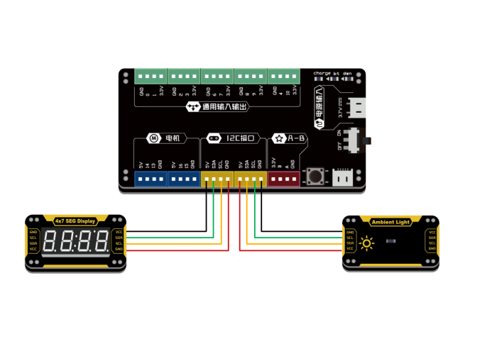
| 实物连接如下图: |
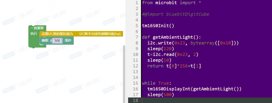
| 程序功能:数码管显示数字光线传感器的测量值 |
版本历史记录
| Version | Date | Note [+]新增[-]删除[^]修复 |
|---|---|---|
| V2.0 |


